User Tools
Sidebar
Navigation
hardware:lan-bridge
Table of Contents
LAN Bridge
The CommandFusion LAN Bridge is the Ethernet & RS232 gateway to the CFLink bus.
Place one LAN Bridge on the CFLink network, then you can access any CFLink device within that CFLink network via Ethernet or RS232.
The LAN Bridge features an on-board real time clock, allowing it to perform advanced scheduling functionality.
Another use for the LAN Bridge is to use it for TCP Socket Multiplexing (connect multiple devices to systems that allow only a single connection at a time over TCP)
Quick Reference Guide
The LAN Bridge Quick Reference Guide provides the basic information required to get started on a printable, black and white document that can be easily taken with you to a job site. Find the LAN Bridge Quick Reference Guide here.
CFLink Protocol
For details on the CFLink protocol supported by the LAN Bridge, see the LAN Bridge CFLink Protocol page.
Information Panel
The information panel can be found on the top of the LAN Bridge.
LEDs
- Power (Blue)
- Off = Power off
- Flashing = Booting or firmware missing
- Solid = Power on and ready
- CFLink Fault (Red)
- Solid = Fault discovered on CFLink bus. Remain solid until reset.
- Reset unit to clear CFLink fault flag and turn off LED.
- CFLink Activity (Amber)
- Flashing = CFLink activity is detected on the CFLink network.
- COM Port Program Mode (Amber)
- Solid = On-board RS232 port is in Program Mode (for communicating with CFLink devices via RS232).
- COM Port RS232 Mode
- Solid = On-board RS232 port is in RS232 Mode (for controlling third part RS232 devices).
- IP Address
- Flashing = Attempting to obtain an IP Address.
- Solid = IP Address has been obtained or statically assigned.
Pinhole Buttons
- Setup
- Press to toggle on-board RS232 Mode
- Reset
- Press to reset the unit. See the Device Resetting page for more information.
Ports
Ethernet
The RJ45 port is used for Ethernet communications. The supplied Ethernet cable can be used to place the LAN Bridge on your local network.
By default, the LAN Bridge is configured to communicate over both UDP broadcasts and TCP Server on port 10207.
RS232
The RJ12 port is used to communicate to and from RS232 devices.
Depending what mode the RS232 port is in (indicated via the information panel LEDs), this port can be used for 2 things:
- Controlling and configuring the LAN Bridge and any other CFLink devices on the CFLink network.
- Communicating with third party RS232 devices such as projectors, TVs, etc.
By default the LAN Bridge is configured to communicate directly with any connected serial device on TCP port 10208.
The LAN Bridge must be set to RS232 mode first (by using the setup button on the top of the LAN Bridge, or via the System Commander configuration software).
Socket and Cable Pinouts
All colors used in the diagrams relate to the wire colors in the RJ12 cable that ships with the LAN Bridge.
If you are using a custom RJ12 cable, then these colors may not match. So check the socket & cable pinouts to relate to your wiring colors.
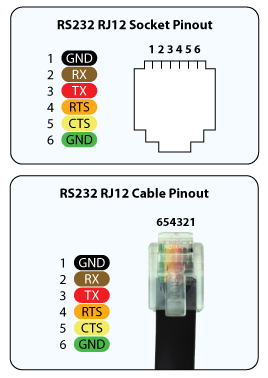
- GND
- RX
- TX
- RTS
- CTS
- GND
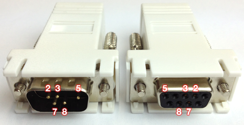
RJ12 Adapter Pinouts
Shipped with the LAN Bridge are two RJ12 to DB9 adapters (one male and one female) and a single RJ12 cable.
These adapters will convert the on-board RJ12 socket to a standard serial port DB9 connector ready for use in most projects.
If you need a special wiring configuration, simply use any off-the-shelf RJ12 to DB9 adapter and configure the wiring as needed.
All colors used in the diagrams relate to the wire colors in the RJ12 cable that ships with the CF Mini.
If you are using a custom RJ12 cable, then these colors may not match. So check the socket & cable pinouts to relate to your wiring colors.

CFLink
The 5-pin CFLink connector is used to communicate with other CFLink devices on the network.
Pinout
- Isolated Ground
- Data +
- Data -
- Power (9-30V DC)
- Ground
MicroSD
The MicroSD slot is used to expand the on-board memory via MicroSD cards.
Accessories
The LAN Bridge comes packaged with the following accessories:
- RJ45 Ethernet cable, 1m, black.
- RJ12 to DB9 male adapter, white.
- RJ12 to DB9 female adapter, white.
- RJ12 cable, 1m, black.
Factory Reset
For information on how to rest your device to factory settings, see the Device Resetting Page.
LAN Bridge Configuration
hardware/lan-bridge.txt · Last modified: 2015/04/16 23:01 by jarrod