User Tools
Sidebar
Navigation
software:third-party-tools:guidesigner-plugins:cbus-plugin
This is an old revision of the document!
Table of Contents
Clipsal CBus Plugin
Please note that this plugin is a THIRD PARTY TOOL is not created by CommandFusion and we offer no official support for it. It is a FREE plugin maintained by members of the CommandFusion community. We can not guarantee the plugin will always be in working order and bug free. We acknowledge that this documentation is incomplete, it is maintained by the developer of the plugin who has other business and personal commitments,.
Please be patient this is a work in progress over next few weeks complete with screen shots etc, so please don't edit till I removed this line, also additions put in over next few weeks will not be done in order, I will being putting instructions on and then tweak.
Before You Start
You must have some basic knowledge of Clipsal Cbus,Cbus Toolkit,and Commandfusion.
You will require the following items:
SOFTWARE
1. Cbus Diagnostic Utility which can be found here.
2. Cbus Toolkit which can be found here.
3. Your Cbus back up project if you did not create it, this will be a file ending with ”.cbz” (not having this is not the end of the world, as can upload your cbus project using Cbus toolkit, you will just be missing the text names associated with the unit addresses.)
4. Cbus Plugin which can be found here.
HARDWARE
There are numerous ways to achieve cbus to ip interfacing and everyone has a personal preference, thus there no need to supply a complete list of every scenario possible in here, including different models of global caches units etc, this is a guide for new users. Below are 3 popular scenarios, for the “how to do” example I will be using scenario (C) which is the 5500PC cbus interface in conjunction with a IP2SL-P Global cache unit.
(A) Cbus PC interface 5500PC. This cbus interface unit will allow multiple user connections,it needs to be used in conjunction with a TCP/IP to serial unit such as a aCommandFusion's LAN Bridge (up to 25 TCP connections, and UDP support). which has RS232 interface,(see data sheet for limitations of multiple connections) and connection is required between the 5500PC and CommandsFusions LAN Bridge. via a RS232 serial lead.
or
(B) Cbus CNI interface 5500CN. This cbus interface unit requires no RS232 interfacing and connects direct to ethernet, but will only allow one user connection at a time. Although if used in conjunction with aCommandFusion's LAN Bridge (up to 25 TCP connections, and UDP support). it will allow TCP Socket Multiplexing then you will be able to connect multiple devices to systems that allow only a single connection at a time over TCP.
or
(C) Cbus PC interface 5500PC. This cbus interface unit will allow multiple user connections, it needs to be used in conjunction with a TCP/IP to serial unit such as a Global Cache IP2SL (see the iTach data sheet for limitations of multiple connections on their devices) and connection is required between the 5500PC and TCP/IP to serial via a RS232 serial lead.
Cbus Setup
Please note: each time you make a change to the cbus project via the PC interface or use a third party app to control cbus, the PC interface settings will change, if you intend to use in conjunction with Commandfusion suggestion would be to use another interface sole used for these otherwise you will have to change settings each time. There is a command which you can add in as initialisation from commandfusion to change the settings for the PC interface to be correct each time you start iviewer but for the example below I have shown the manual setup.
CBUS 5500PC SETUP
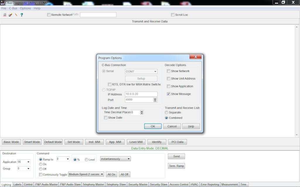
Before you begin you must have the Cbus PC interface 5500PC set to network address 254 this will be set through Cbus Toolkit which can be found here.. Plug your PC via serial lead into the Cbus PC interface 5500PC. Then run Cbus Diagnostic Utility. Once open go to “OPTIONS” then another window will open then select “PROGRAM OPTIONS”, then check box which is your method of connect then click “OK'. In this example I am using serial and com7 as per below screenshot.
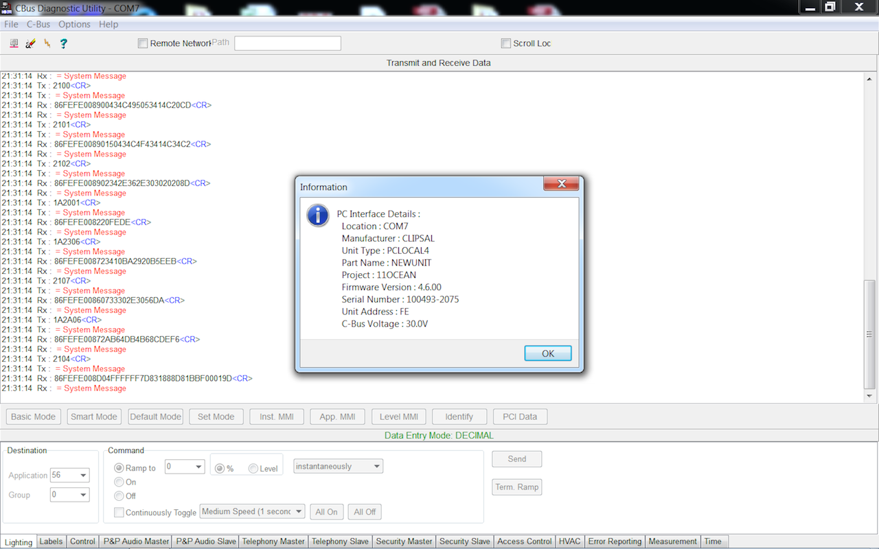
Now to connect to the Cbus PC interface 5500PC to make the relevant setting changes to allow CF to talk to the CBUS network go to “CONNECT”,a drop down box will appear then select “CONNECT TO CBUS”, you will see a tick next to the “CONNECT TO CBUS” once you have clicked on it.A list of messages will scroll down the screen and finish with a window with some PC interface details as per below screen shot. Once pop up window has appeared click “OK”.
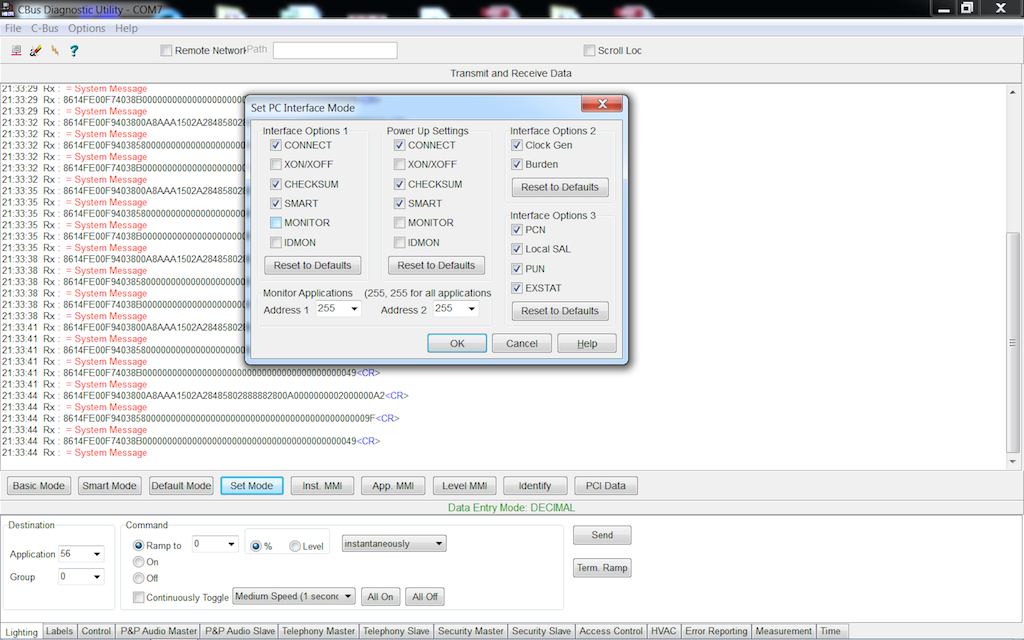
Once the popup window disappears, scroll down to the middle buttons and click on “SET MODE”, and make the settings as per below screenshot. OPTION 1 must have “CONNECT, CHECKSUM, SMART” ticked, OPTION 2 has no bearing on the CF plugin if selected or not, please read cbus documentation or contact installer if you require these to be selected or not. OPTION 3 requires EXSTAT only selected, the other option are for your personal preference for your cbus system.
Commandfusion Systems and Cbus Toolbox
CREATE YOUR SYSTEMS
Once you have created a project you need to create two systems, the first will be “cbus” this is the name of the cbus.js script, the system must be exactly as per the script name and it is case sensitive. Note: The startup macro will be placed in later and described later. The second is “broadcast”. Inside the “broadcast” feedback will have to be created the regex will be “cbus:..:..:..;”
Important note: the system names and feedback names must be named as per screen shots
System “cbus”

System “broadcast”

System “broadcast” feedback note: regex will be “cbus:..:..:..;”

CBUS TOOL BOX
Once the systems are created, open the cbus toolbox as per below screen shot. Once toolbox is open we will proceed to find your cbus file.

To find your cbus file, notice the the C-Bus XML file tab on the above screenshot, click on the browse button, follow the tree as per below screenshot and find your cbus project.

Commandfusion Adding the Project
CBUS PROJECT INTO COMMANDFUSION
Before you add your cbus project into commandfusion there are some steps to follow and understand,

System
First step is to click on the reload button to the right of system, this will refresh any systems you have added. once refreshed click on the drop down box and select the “cbus” system.
Lighting and Trigger base joins
These determine the joins that will automatically be elected once you add your project, these joins will include analogue, serial and digital joins, for this example we have chosen to use 5000 for the individual lights and the 6000 will be for the scenes, joins are very important to how the JS was written and triggers lighting not only for the lighting feedback so make sure you choose empty joins.
Level Display
This drop down gives the option to how the level is display in serial text if used.
Cbus
levels range from 0-255, being 0 is off and 255 is on, if light is dimmed to halfway it will indicate 127.
Percentage
level will be indicated as a percentage 0% is off 100% in on, if a light is dimmed to halfway it will indicate as 50%.
Project
This is the final step before you click the “ADD” button, as you can see from below screenshot there are some tick boxes, if you open the tree you will see your cbus project name in this example it is called “BSHORT”, then under this will be you network (254), the next step down in the tree will be lighting (56) and trigger control (202).
NOTE: Depending on your cbus project you may see other options as enable control (203) or other networks with other address such (243), currently the cbus module only allows network (254) and also only allows for lighting (56) and trigger control (202) under this network. Other options may be offered in further releases.

If you tick the highest box in the tree this will select everything below it in the tree to add, however if you only want to add part of you cbus project you can open up all the boxes including down to the point of individual lights or scenes for selection.

ADDING THE PROJECT AND OPTIONS
Now you have decided upon you options and how much you want to add, the next step is to click on “ADD”, once you click on “ADD”, a task complete box will show, once you click “OK” the items will be added into the “cbus” system, we are now ready to add commands to buttons.
 }
}
Adding The Commands
SYSTEM COMMAND TYPES
As per the below screenshots you will notice 4 different types of commands: Level, Toggle, Ramp and Scenes, you will notice that the cbus names and addresses are the same for ramp and toggle, this will be explained further.
Level
This is a command to be send out as a get or refresh command, the (56) command is the individual light level command and the (202) is the scene commands, this should be placed in a macro and placed into the cbus system startup command macro as per screen shots, further to this you can add it into your main js to run the macro upon wake up.

Below is the macro with the delays required

Below is where to add the macro into the system for startup

Toggle and Ramp
These commands are actually tied together in the cbus JS and are required to be placed onto a button and a slider to work, even if a slider is not required in you gui, this is explained further.


Scenes
This command is used to trigger scenes that you have created in your cbus project toolkit, this command is not required for the cbus js to work, it is up to yourself if you use this.

ADDING THE COMMANDS TO BUTTONS
Individual lights
To make a light work, you will require a single button (on/off state) and a slider, the way the JS module is written you will require both the toggle and the ramp of the system for it to work. Even if you do not require the slider as the light you are trying to control is just on / off, a slider will be required, this can be placed on a cache page in your gui project and not ever brought to screen.
Buttons
Below I have shown the toggle command property, notice the (56,1)in the JavaScript box, we are only interested in the 1. This is the address we need for feedback and control.

Next create you preferred button and drag the command into the button or open the button properties and select your command. NOTE: make sure you use the “toggle command” not the “ramp” command. Once you have selected the lighting command you want in the digital join place 5001, the 5000 part of the address is the base address join we selected earlier in Commandfusion Adding the Project - Lighting and Trigger base joins prior to adding the cbus to cbus system in commandfusion, the 1 portion of the address is the address of the cbus light which was shown in the above screen shot.

software/third-party-tools/guidesigner-plugins/cbus-plugin.1443343486.txt.gz · Last modified: 2015/09/27 08:44 by dogs_au